Assembly Drawing 1 Screwjack. Bearing housing VDMA 357 with the help of a gear puller bearing VDMA 320 or 323 if roller type spacer ring VDMA 505 the elastic ring VDMA 935 at non-drive end and only when roller bearing is.

Internal Gear Pump Assembly Spare Parts In A10vg45hw1 10r Nsc10f013s S Mh Hydraulics
To get the best from the pump carefully read and understand this manual before installation and start-up.
. Assembly Drawing 2 Tailstock. This video make by Vishwakarma Engineering Drawing Classes Bhilai Nagar. 0 In order to download this file you should sign up and make a contribution.
Assembly Drawing 9 Cylinder Relief Valve. Assembly Drawing 4 Gear Pump. Table of Contents Description Pg 020 Series Exploded View 5 Shaft End Covers 6 Drive Shaft Gear Sets 7-8 Gear Housings 9-12 Bearing Carriers 12 Gear Sets 12 Port End Covers 13.
When the gears rotate the liquid which is trapped in the gear teeth spaces between the. Pump assembly from vehicle and plugging ports. Hydro-gear a world leader in turf care transmission products.
Albany gear pumps are available in many configurations whilst they may look the same there may be differences from one pump to another and therefore supplementary instructions can be supplied. 2 Put a location mark across front plate bodies adapters. End view one half of outside view looking on gland with coupling removed the other half a section through the pump casing looking at the ends of the pinions.
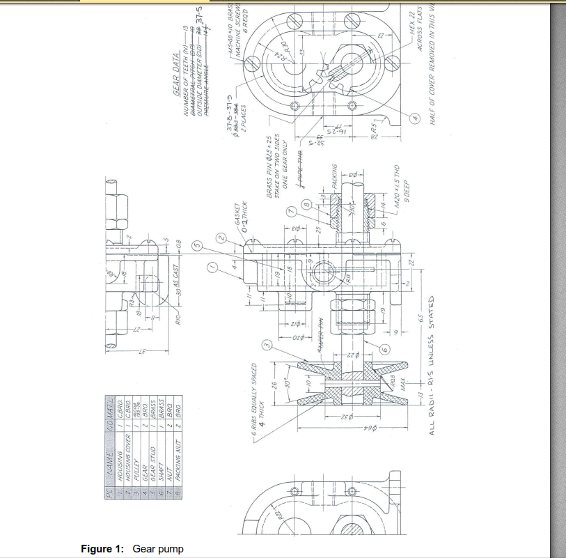
10 - Parts list 11 - Sectional drawings and auxiliary drawings. On this drawing the location and dimensions of few important parts and overall dimensions of the assembled unit are indicated. 3 Series 26 - Model 26000 Multiple Gear Pump Pump Parts List Displacement Item No.
After cleaning remove port plugs and drain oil. Gear pump assembly drawing. Disassembly procedures for variable pump reconditioning and replacement of parts assembly procedures for variable pump parts drawing parts list.
Assembly Drawing 5 Valve. 1 Remove key from drive shaft if keyed drive gear assembly is used. A step by step sequence followed is attached as a document you.
Five Section Gear Pump Assembly. The gear pump is a precision machine with extremely tight fits and tolerances and is capable of working against high differential pressures. Series 26 - Model 26000 Single Gear Pumps Parts Drawing Righthand CW Rotation Pump Lefthand CCW Rotation Pump 3 Body 1 Front Plate 11 Cap Screws 17 Washer 8 O- ring 8 O-ring 40 Plug 12 13 Backup Gasket 7 Seal Wear Plate 4C Drive Gear 5 Assembly Idler Gear Assembly 10 Washer L R 9 Shaft seal 25 Optional Retaining Ring 4A Drive Gear Assembly 4D.
Thoroughly clean the outside of the pump. This drawing provides useful information for assembling the machine as this drawing reveals all parts of a machine in their correct working position. Drawing Title Part Number Description.
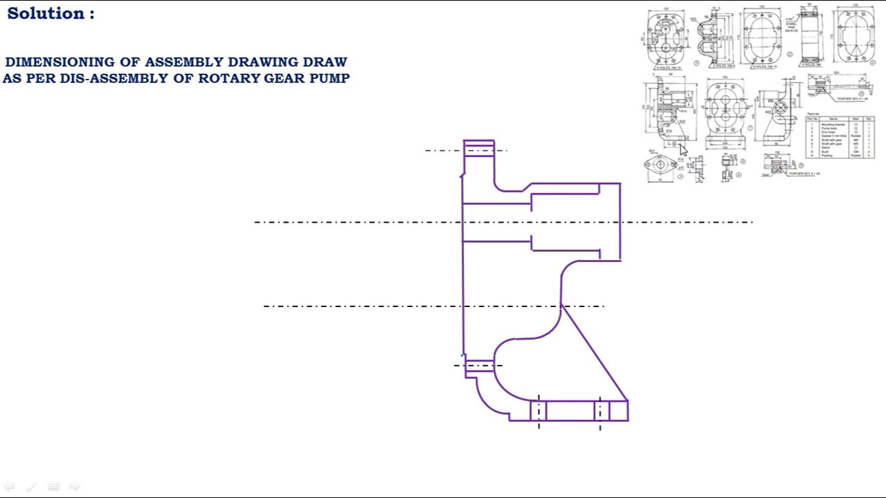
Here you can learn to draw an assembly drawing of a Gear pump in just 5 min. Also include a bill of material. 34 28 Body Width Item No.
English 3353-931 Service Bulletin. Assembly Drawing 6 Fuel Pump. 67 29 Item No.
Russian HydraulicsPneumatics Compass Educational Added. Bdp-10l variable pump variation chart. Assembly Drawing 7 Starting Air Valve.
BCH 9000 from 005 to 24 ccrev. Disassembly of a Triple Pump During disassembly keep all mating part in order and together. Parts Book P20-P5051-P7576-P315 Gear Pumps and Motors Distributor Program.
Czb Series Ss Magnet. Pump is shown in Figure 1 where the arrows show the direction followed by t he fluid between t he inlet and outlet of the hydraulic unit. 7 - Pump assembly 71 - Assembly of pumps with outboard ball.
A drive gear that is driven by a motor rotates an idler gear in the opposite direction. Download Parts Catalog Manuals Warranty. Assembly Drawing 8 Fuel Injector.
1234 Installation Assembly Drawing. Search for a part within assembly drawings. Sectional elevation through longitudinal axis of driving shaft showing an assembled pump.
To disassemble or assemble a double pump the center assembly shown here will be eliminated. Assembly Drawing 3 Crane Hook. Drawing Of Gear Pump.
All the best Pump Drawing 39 collected on this page. BCH 9000 from 15 to 30 ccrev. Pump Parts Drawing Triple righthand CW rotation pump shown.
44 49 Item No. The working principle of the external gear pump is illustrated in Figure 1. Up to 5 cash back Introduction to Assembly Drawing.
Ems Ram Pump Drawing. BCH 9000 from 45 to 90 ccrev. BCH 9000 from 45 to 9 ccrev.
Of an Albany gear pump. Up to 5 cash back Draw the following assembled views of gear pump. 26 45 cm3r in3r Body Assembly mm in.

Gear Pump Exploded Exploded View Drawing Wikipedia The Free Encyclopedia Hydraulic Systems Gear Pump Hydraulic Pump

Drawing Of Gear Pump Used In The Ried Test To Explore Undergraduate Download Scientific Diagram

Gear Pump Assembly 29 Download Scientific Diagram

Solidworks Drawing Tutorial Gear Pump All Drawings In One Sheet Youtube
Background Figure 1 Shows The Arrangement Of A Gear Chegg Com

Gear Pump Assembly Youtube

The Gear Pump Assembly In A 3d Exploded View Download Scientific Diagram
Assembly Drawing Of Rotary Gear Pump Youtube
0 comments
Post a Comment